CMM2000 Help - Profiles Window - Cylindrical Cam


|
CMM2000 Help - Profiles Window - Cylindrical Cam
|
|
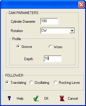 Inside the Dialog Box defining the
CYLINDRICAL CAM it is possible to define the
Tool Diameter and enable / disable the option
Cutter Radius Offset.
These conditions are used for calculation the Tool
Path in order to work the Cam profile on a CNC
machine.
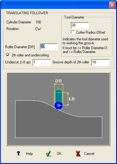
Only with Translating follower, worked with a
tool having the same diameter of the Roller it is
possible to use the 2D profile exportable from the
Profiles window .
In all the other cases there are necessary further
specific informations as follows.
|
 | |
|
| ||
|
CASE 1
The operator gives : Roller Diameter = 0 and Tool
Diameter = 0
It is a limit case, it is generated only a Cam Profile
representing the track of the centre of any roll for any tool
diameter. Inside the Data window are presented the
informations regarding the tool centre, used for the CNC
in the format : Angle, X, Y, Z
The option “Cutter Radius Offset” has no effect.
|
CASE 2
The operator gives : Roller Diameter ≠ 0 and Tool
Diameter = Roller Diameter
Inside the window Profiles will appear two profiles
representing the Upper Cam Profile and the Lower Cam
Profile. Inside the Data window are presented the
informations regarding the tool centre, used for the
CNC in the format : Angle, X, Y, Z
IMPORTANT: It is impossible to mill the Cam Profile
with a tool having a different diameter in respect to the
Roller Diameter previously defined.
The option “Cutter Radius Offset” has no effect.
| |
|
CASE 3
The operator gives : Roller Diameter ≠ 0 and Tool Diameter defined as follows :
Roller Diameter > Tool Diameter > Roller Diameter / 2
If the option “Cutter Radius Offset” is disabled inside the Profiles window will appear two profiles representing
the Upper Cam Profile and the Lower Cam Profile.
Inside the Data window are presented the informations regarding two tracks for the tool center, used for the CNC
in the format :
Angle, X, Y, Z regarding the milling of the lower track of the Cam Profile.
Angle, X, Y, Z regarding the milling of the upper track of the Cam Profile
IMPORTANT: It is impossible to mill the Cam Profile with a tool having a different diameter in respect to the Tool
Diameter previously defined.
If the option “Cutter Radius Offset” is enabled inside the Profiles window will appear two profiles representing
the Upper Cam Profile and the Lower Cam Profile.
Inside the Data window are presented the informations regarding two tracks on the Cam Profile, used for the CNC
in the format :
Angle, X, Y, P, Q, Z regarding the milling of the lower track of the Cam Profile.
Angle, X, Y, P, Q, Z regarding the milling of the upper track of the Cam Profile.
NOTA:
Since the Data are regarding the nominal Track surface of the Cam Profile, it is possible to use any
Tool Diameter < Roller Diameter.
a ) The CNC must be enabled to use the function G41, G40, G42 (Enabling Cutter Radius Offset) jointly
the use of a rotating axe; in this case use Data in the format Angle, X, Y, Z .
b ) The CNC must be enabled to use, in parametric mode, the values assigned to P and Q indicating
the
parametric corrections for X and Y ; in this case use Data in the format Angle, X, Y, P, Q, Z
| ||
 | ||
|
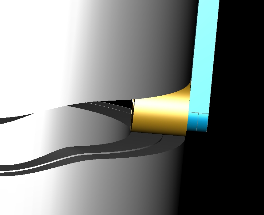
Example of a Cylindrical Cam with Translating follower and Groove track.
In this specific case, the "Groove depth of 2th roller" option has been activated, which
allows the solid to be defined so that a hypothetical double roller does not touch
the upper and lower track at the same time.
| ||
 |
|
Example of a Cylindrical Cam with Translating follower and Worm track.
|
|
| |
|
|
|
|
| |