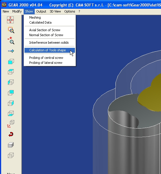
Calculation of tool shape
CAM SOFT s.r.l. has introduced a new procedure for the calculation
of grinding wheel profile and
End-Mill tool shape for piece machining.
-MENU _ Show_ Calculation of Tools shape -
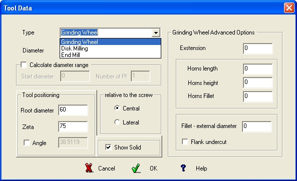
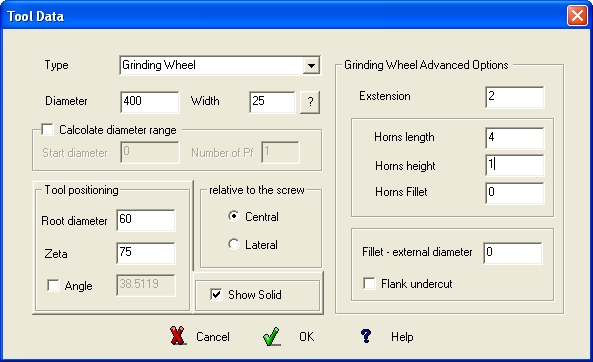
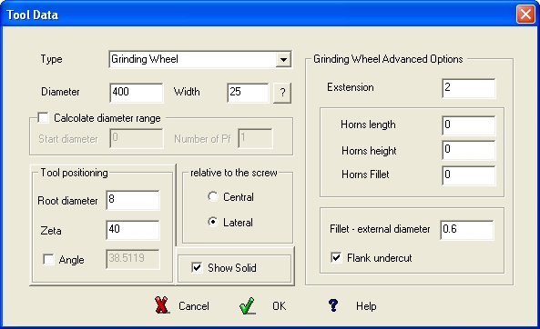
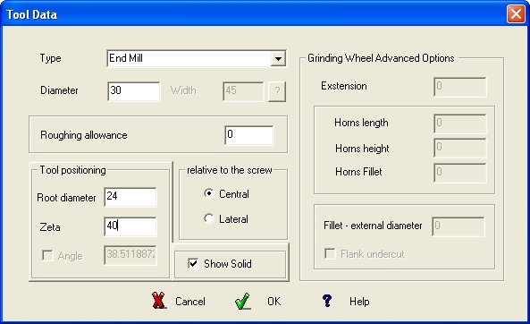
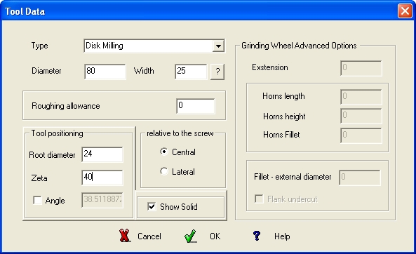
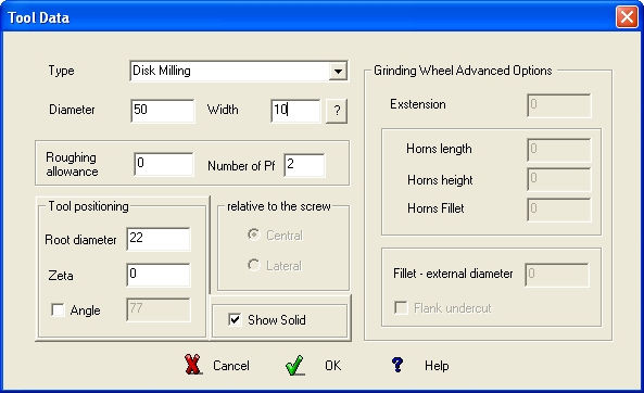
- Tool Data DIALOG -
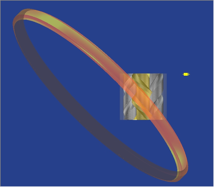
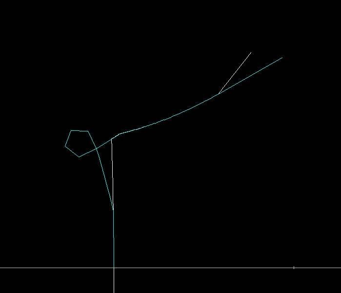
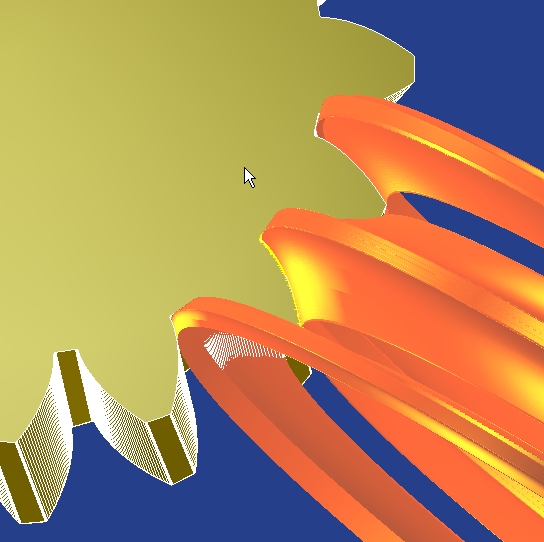
After entering the values in the DIALOG, pressing OK creates and displays the Simple Solid of the
tool with the cloud of points (yellow to the left in the images below) for creating the geometry of
2D profile.
|
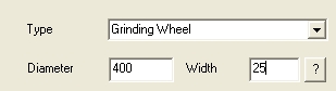
Options for calculating the wheel width and modification of the tilt angle.
|
|
|
|
|
Clicking ? button the software proposes in the
Width box an approximate value to use for
calculating the grinding wheel. At the end, a
confirmation menu it will display the effective value
that can be inserted in the Width box.
|
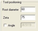
If the tool tilt is different to the helix angle,
you can enter the value by activating the
Angle check-control.
|
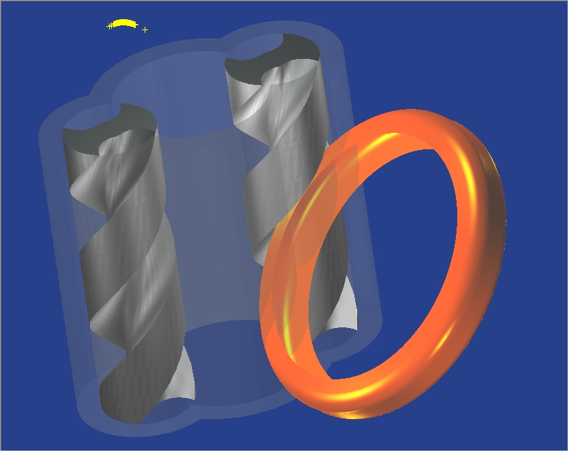
-Simulation of solid screws, grinding wheel and cloud of points -
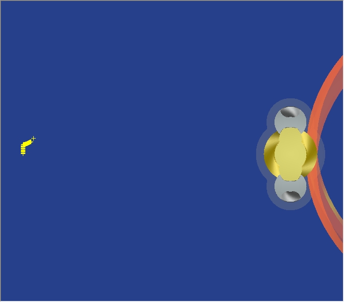
- TOP view of solid screws, grinding wheel and cloud of points -
Grinding Wheel Advanced Options
Entering the values in the 'Grinding Wheel Advanced Options' area, you can get automatic
changes when creating the geometry of the tool.
Example:inserts Extension value, to extend the extremes of wheel profile.
Output is a text file for Numeric Control and a CAD file in DXF or MI format for exporting the
wheel profile. (Data and 2D/3D files).
The Customize item of Options menu contains the default values associated of Tool Data DIALOG .
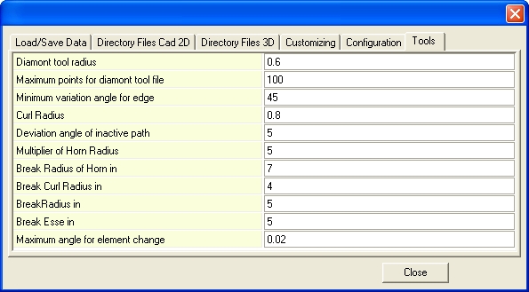
- 'Tools ' folder of Customize menu -
Calculated points are thinned in order to contain the machining within the parameters required by
the Numeric Control ('Maximum points for diamond tool file').
Points thinning takes place with the criterion of keeping dense information in contour areas such
as concavity changes, bending radius, chamfer, in accordance with the inserted 'Diamond tool
radius'.
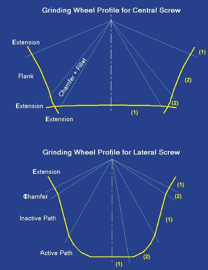
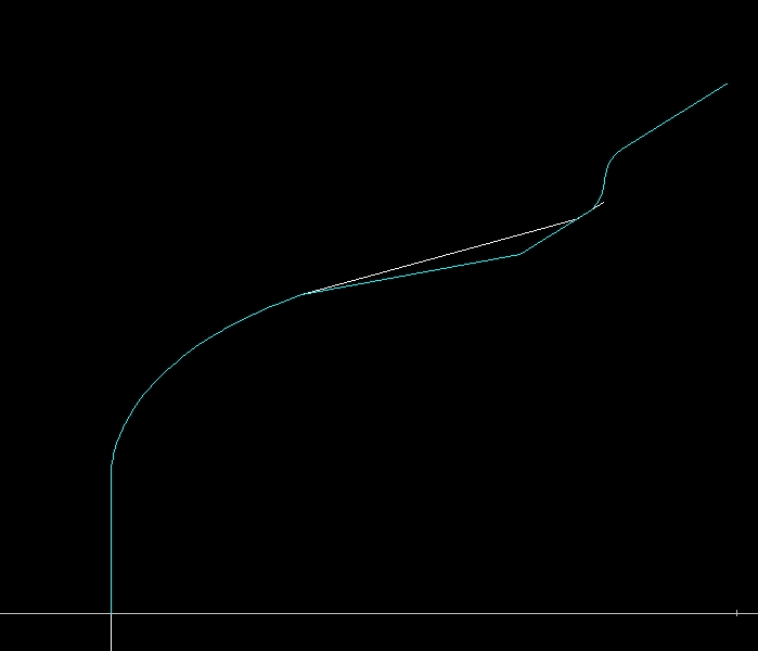
- Characteristics of grinding wheel profiles for central and lateral Screws -
In the left part of the profiles, the characteristic features of the contour are indicated, while in the
right part are indicated the thinning areas (1) and the areas with the highest density of points (2).
All points whose angular deviation from the previous element does not exceed the 'Maximum
angle for element change' value, are deleted.
'Horns Fillet' identifies the radius in the corner found where the original profile deviates from a
greater angle than 'Minimum variation angle for edge'.
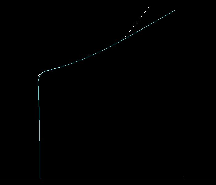
- Original profile (white) and modified profile with Horns Fillet + Extension (cyan) -
Since the diamond can not perform arcs, the inserted fillet is broken into segments of length
equal to 'Break Radius in' value.
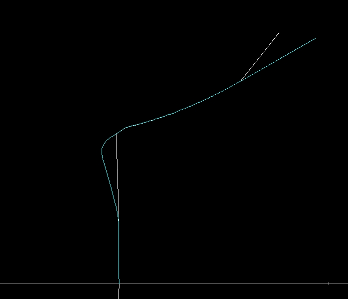
- Original profile (white) and modified profile with Curl Radius + Extension (cyan) -
Multiplier of Horn Radius defines the vertical deviation before curl to obtain the sharp edge.
Since the diamond can not perform arcs, the 'Break Curl Radius in' value allow to break into
many segments.
When Horns length<>0 and Horns Fillet=0 you are asked whether to create 2
separate files with extensions Dxxx and Sxxx (the only way to obtain the sharp
edge). Answering no, a single file is created that generates the sharp edge with
the insertion of the curl.
- Original profile(white) and modified profile with Horns Fillet + Extension (cyan) -
Multiplier of Horn Radius defines the vertical deviation before curl to obtain the sharp edge.
Since the diamond can not perform arcs, the 'Break Radius of Horn in' value allow to break into
many segments
- Original profile of grinding wheel for later screw (white) and modified profile with Flank undercut + Extension + Fillet-external diameter (cyan)-
The inactive path is modify using 'Deviation angle of inactive path' value.
If 'Fillet-external diameter' value is greater than zero, the double curve (Esse) is inserted to
profile extension; 'Break Esse in' value allow to break fillet radius into many segments
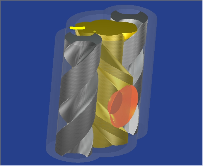
- View of End-Mill machining mode -
The screw rotates around axis A while the mill rotates around axis B.
- 3D solid of End-Mill tool for central screw -
- 3D solid of End-Mill tool for lateral screw -
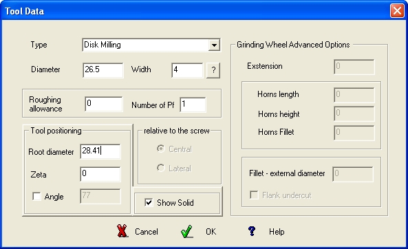
Disk Milling Tool
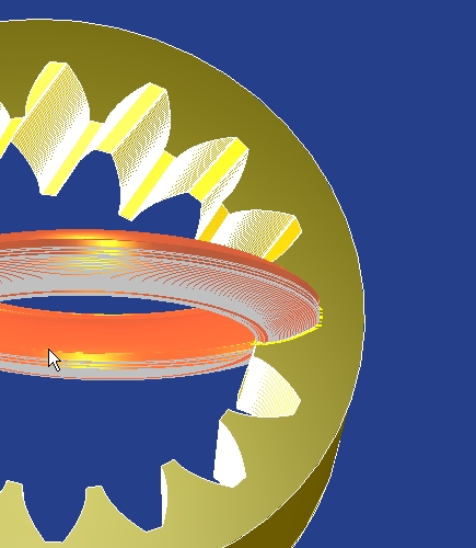
- 3D solid of Disk-Milling tool for central screw -
- 3D solid of Disk-Milling tool for lateral screw -
To make the solids transparent click on one of the solids and press the CTRL key by rotating the
mouse wheel.
Right-click and use the drop-down menu to select objects that you want to view / hide completely.
Since it is possible to use the tool calculation also for the machining of worm gears, it is good to
know that from version 5 the software also calculates the tools for the machining of internal
gears and is able to calculate tools that work several spaces simultaneously.
To work on multiple spaces, it is necessary to define a Number of PF greater than 1 and
indicate a tool Width sufficient to encompass the area to be worked.
GEAR2000 Help