Output Data and
Export 2D\3D files
Once the solids are generated, the display commands appear in the left part of the main window,
also available in the drop-down menu that appears when you CLICK with the right mouse button
on the background.
At the same time,
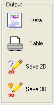
Output commands are activated in the right part of main window.
-Output commands -
 Data
Data
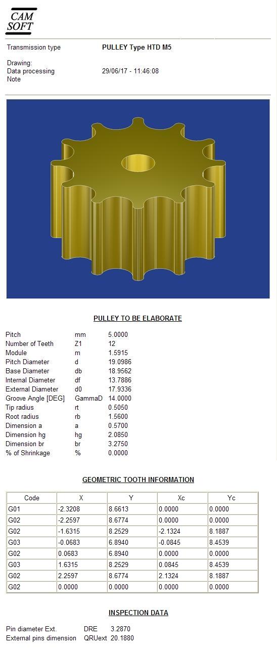
Shows and Saves the project data into HTML document.
Use a browser program like Internet Explorer, Firefox, Google Crome or other to open stored file.
From 4.04 release it is possible to customize the graphic look , inserting your company
logo at the top of the pages
To do this, just replace the c:\cam-soft\gear2000\images\html_testa.bmp file with the file
containing customized logo.
-Example of HTML format data output -
 Save 2D
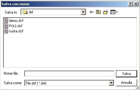
Exports geometry to CAD 2D format file MI,DXF or TXT.
Enter a new name in the File Name box or double-click the existing name with the left mouse
button.
The save directory (Save in: dxf) can be customized using the Customize command in the Options menu.
The exported profile is related to the active object in the 3D window; If multiple objects are
displayed, you must choose one, left-click on the mouse.
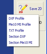
? DXF Profile , formatted file for AutoCAD® .
? Me10 MI Profile , formatted file for ME10® HEWLETT-PACKARD® CAD.
? TXT Profile , text file containing Cartesian coordinates X,Y.
? Section DXF and
? Section Me10 MI are also available .
In the specific case of the grinding wheel tool, since output is made not of a single file but of more
than one, the user specifies only the name that indicates the 2D MI or DXF profile but the
software generates all associated files automatically.
The user must create any new folders useful to separate the various files (for example, a
complete grinding wheel series for working a central screw).
In the case of the probing, the output consists of 2 files: the corresponding section (DXF or MI)
and a .mca text file containing 6 values for the position and direction of the vectors to be used for
the probe
 Save 3D
Exports 3D solid object to IGES3D, STEP, STL and VRML formats for CAD 3D modeling
programs.
To select multiple objects to export, you must click them individually or in groups by holding down
the SHIFT key.
In some complex specific cases (eg. screw pumps), all active items are stored without the need to
make the selection.
The save directory can be customized using the Customize command in the Options menu.
GEAR2000 Help