Configuration and Customization
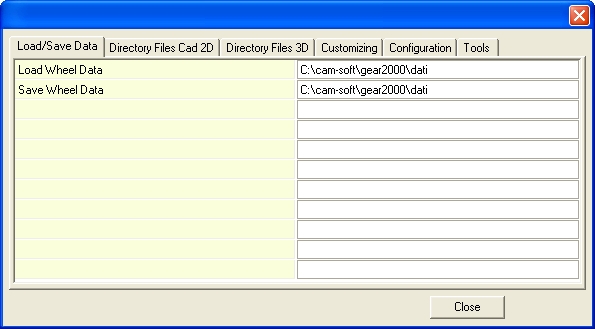
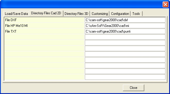
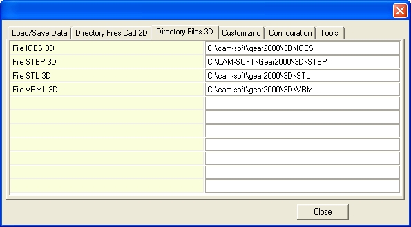
DIRECTORY
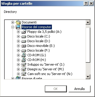
Clicking in the white space behind the current folder, the button  appears.
 Program shows a DIALOG-BOX that allows to browse the file system and change directory.
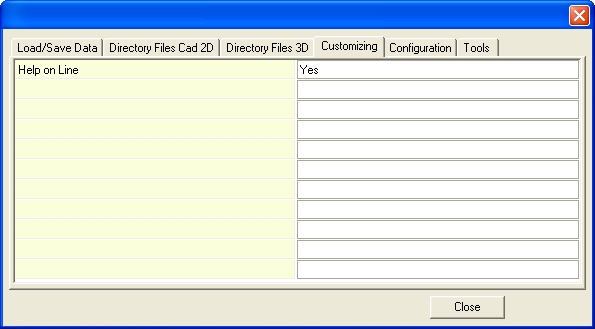
HELP ON LINE
Help on Line : Yes/No : if =Yes when the mouse cursor stops for a
few seconds on a
command icon, a popup describes how it works.
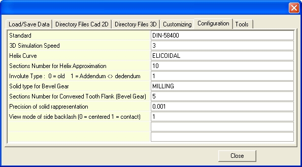
VARIABLES
Standard :
default standard for tooth profile construction.
3D Simulation Speed : min 1 max 10 : indicates the solids rotation
speed during simulation.
Helix Curve : Defines the calculation method of the solid in the case of a helical wheel
Use STRAIGHT option to obtain the solid suitable for cutting with EDM.
High and low profiles are connected by a straight generator.
Use ELICOIDAL or THRU SECTION to obtain the solid suitable for milling machining.
High and low profiles are connected by a polyline or spline.
The next value Sections Number for Helix Approximation is required.
Involute type :
0/1
: if =1
number of points over pitch diameter is not equal to number of
points
under pitch diameter.
Solid type for Bevel Gear : Defines the calculation method of bevel gear
EDM WIRE : High and low profiles are projected
onto the cutting plane
for the machining with wire EDM.
MILLING : the
solids is made for MILLING machining.
Sections Number for Convexed Tooth Flank (Bevel Gear):
Defines the number of sections used to apply to tooth shape the bending needed to ensure
contact on the central part of its length.
Precision of solid rappresentation:
Defines the accuracy of the displayed solid (not the generated one, and then exported to the 3D
CAD file).
View mode of backlash :
0: during simulation the pinion tooth is centered respect to the wheel space
(the backlash is visible equally distributed on all sides).
1: during simulation pinion tooth and wheel tooth are in contact;
the total backlash is all displayed between pinion and wheel flank.
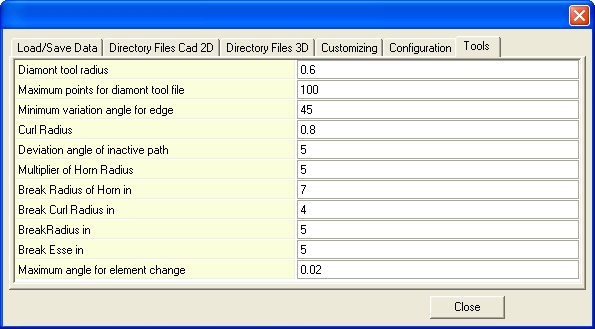
TOOL SHAPE CALCULATION
GEAR2000 Help