For the calculation of the profile is proposed a method, with parametric mode, which uses the
minimum amount of INPUT.
The analysis, it is independent of any design activity.
This type of pump has the following benefits:
1. Large capacity.
2. Conjugated profiles in contact or in proximity to continuous contact.
3. The most frequent use appears in the dry carter motors for suction of the lubricant and its
vapors from the engine carter.
Further uses are found in the textile industry for hot air blowing for the drying of fabrics.
Since the reversible Root Compressor can be used as a compressor or as a pump, it is
therefore a great use in measuring flow rates.
4. It is not necessary to lubricate the contact between the rotors but it is possible to maintain
a
controlled clearance; there is no sliding in the relative motion between the conjugated
surfaces. To optimize performance, the same minimum clearance must be maintained
between rotor and carter.
5. The position between rotors is made using gears with transmission ratio 1 : 1.
6. Among the disadvantages it is worth noting that the instantaneous flow rate is not constant.
4 types of profiles have been developed, all with the possibility of generating the helix:
1. ROOT Cycloidal Lobes.
2. ROOT Modified Lobes.
3. Bi-Ali.
4. Enveloping + Arcs Lobes.
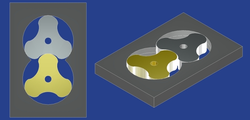
1. ROOT Cycloidal Lobes.
The diameter and the conjugate profiles consist of Epicycloids and Hypocycloids for each lobe.
The fundamental dimension is the distance between the two rotors IY , the two primitive circles are
always supposed to be equals, he sum of diameters C1 + C2 is equal to IY.
Also the diameters of R1 , R2 ..... Ri are equals.
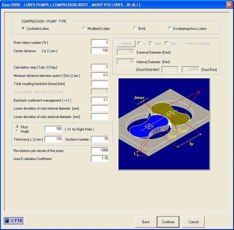
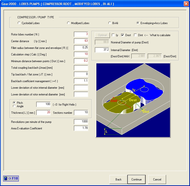
IY : center distance between rotors.
Calc : Calculation step [DEG].
Dist : Minimum distance between points calculated with Calc value (suggested 0.2 mm).
JMAX : Max coupling backlash; this value allows to define the Offset value applicable to profile:
Off = ( JMAX - ( 0.min - 0.max ) /2 ) * K
K (Backlash coefficient management) is a user parameter that aims to ensure the presence of a
minimum clearance even when Iy is made with the minimum deviation value.
K must be > 1 and is suggested = 1.1
Thickness, Pitch/Angle and Sections number allows to define helix features for solid model if Solid or Simple Solid options are chosen.
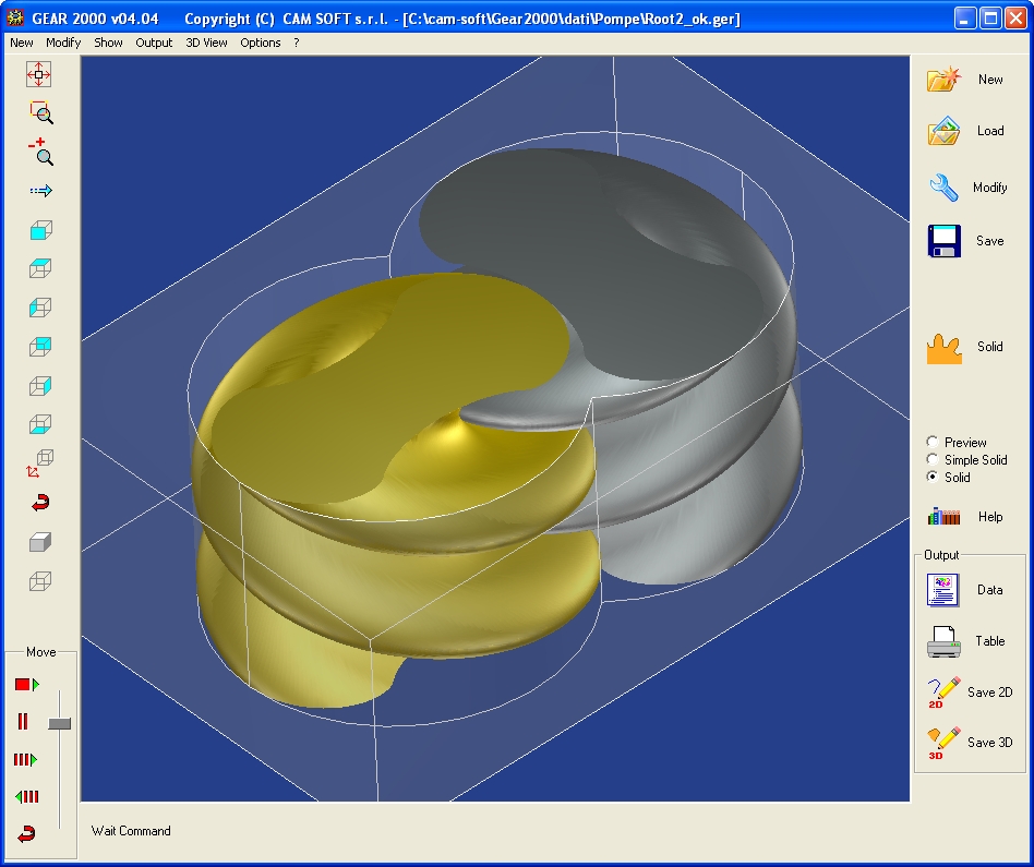
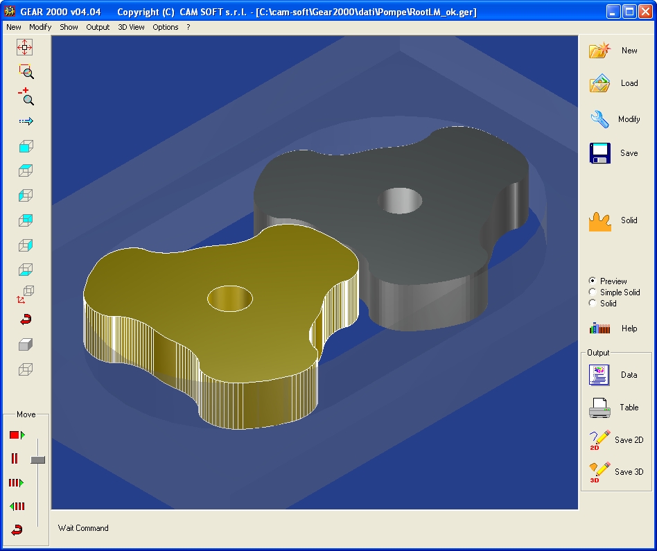
-ROOT Compressor 2 Lobes with helix -
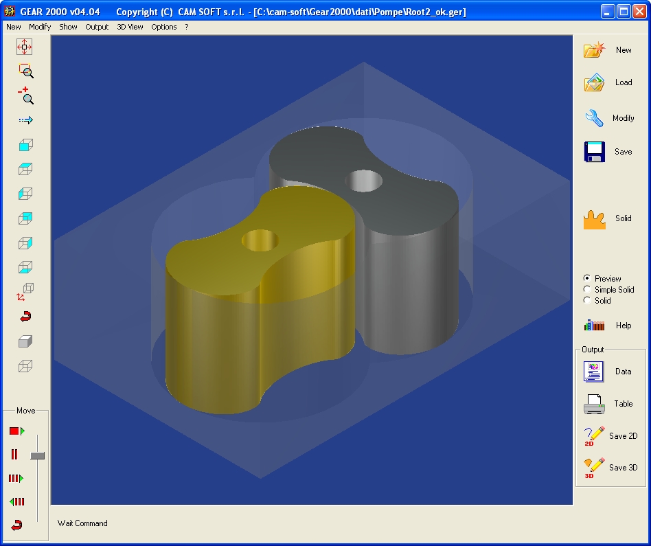
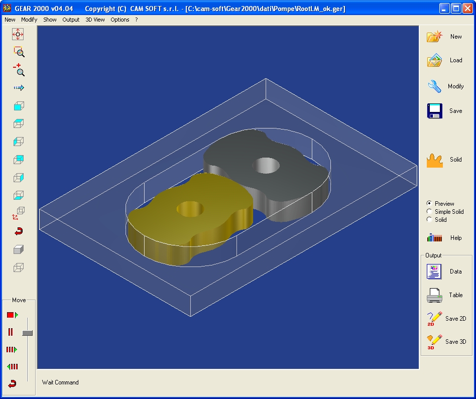
- ROOT Compressor 2 Lobes , Preview -
2. ROOT Modified Lobes
Compared to the normal ROOT, ave a different Dint/Dest ratio.
- ROOT Compressor 2 Modified Lobes , Preview -
- 3 Lobes -
3. Bi-Ali Lobes
For non-fluid materials.
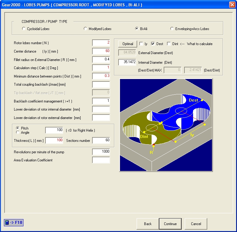
- Bi-Ali DIALOG -
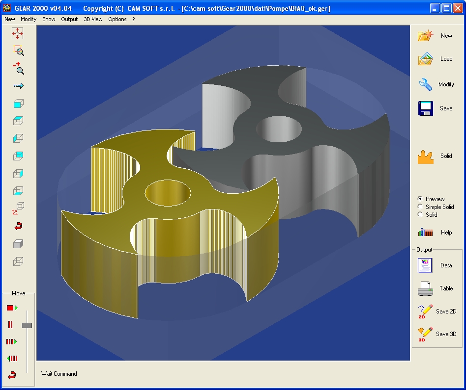
- Bi-Ali 3 Lobes , preview -
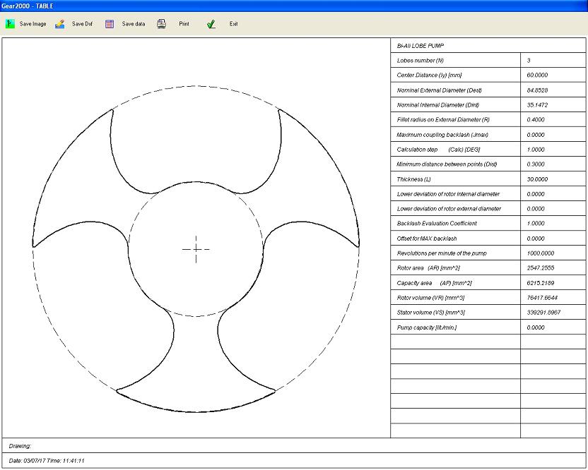
- Table -
4. Enveloping + Arcs lobes pump
In this case, where possible, an entire circle arc is inserted.
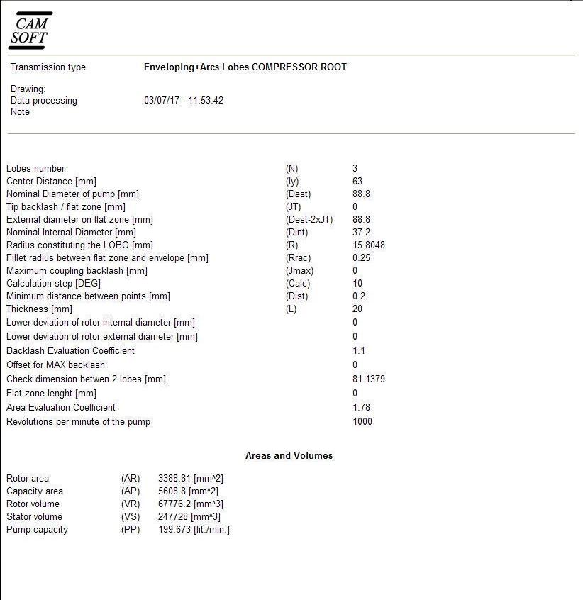
- HTML report -
Pump capacity :
Pump capacity is calculated using lobes number, area/volume dimensions and safety value
Area Evaluation Coefficient (suggested = 1,78 ).
Its measure unit is liters / minutes.
GEAR2000 Help