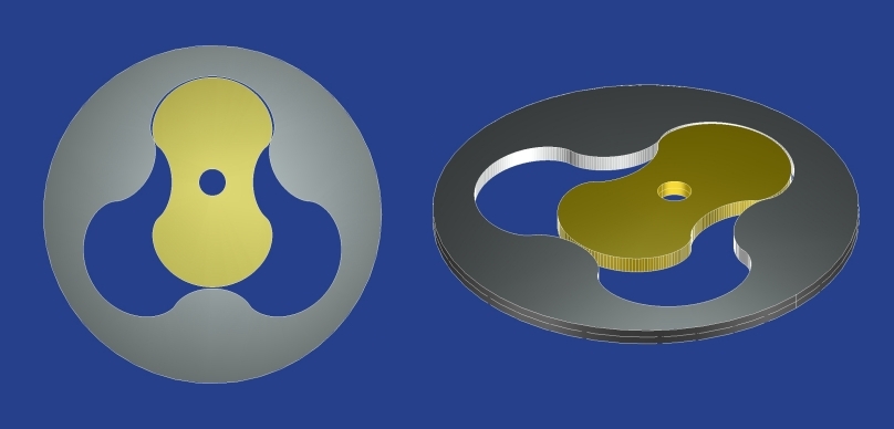
Cycloidal lobes compressor pump
Geometric elements of the inner rotor are known CYCLOIDAL curves and the profile is self-built
by the data provided in INPUT.
The inner rotor is made of a portion of Epicycloid and a portion of Hypocycloid.
Epicycloid and Hypocycloid generation rolls can have different diameters.
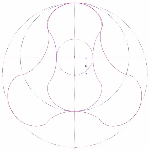
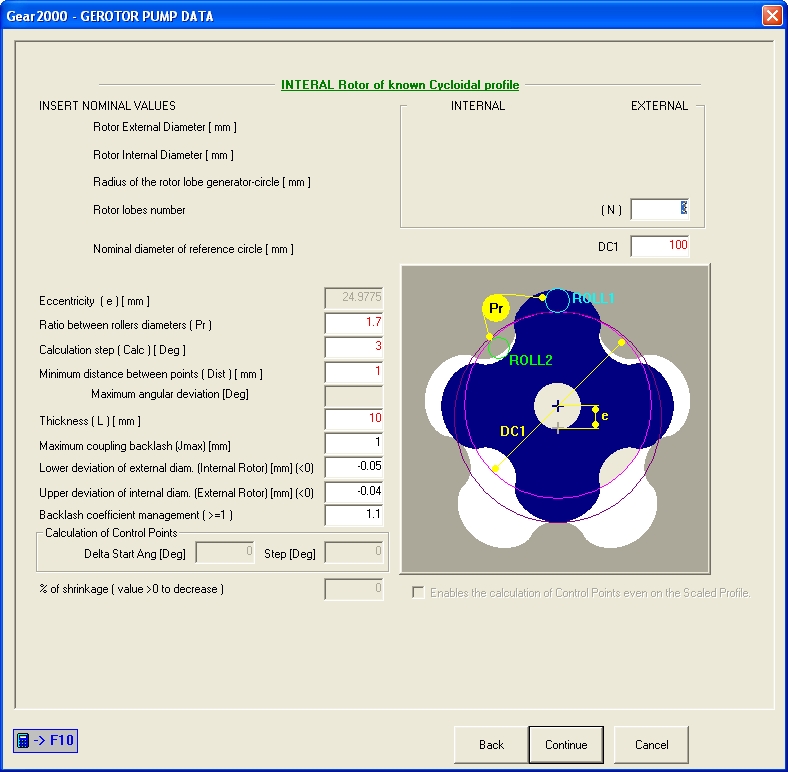
The fundamental features are defined by the value of
Nominal diameter of reference circle (DC1), Eccentricity (e)
and internal Rotor lobes number (N).
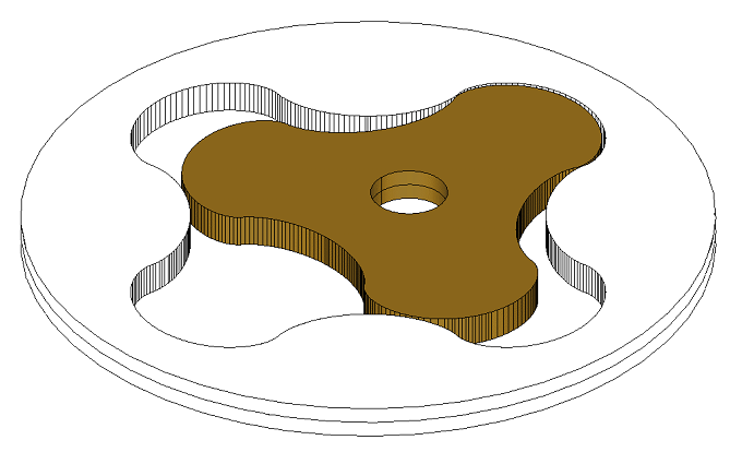
External and Internal diameter of internal rotor are calculated from input data.
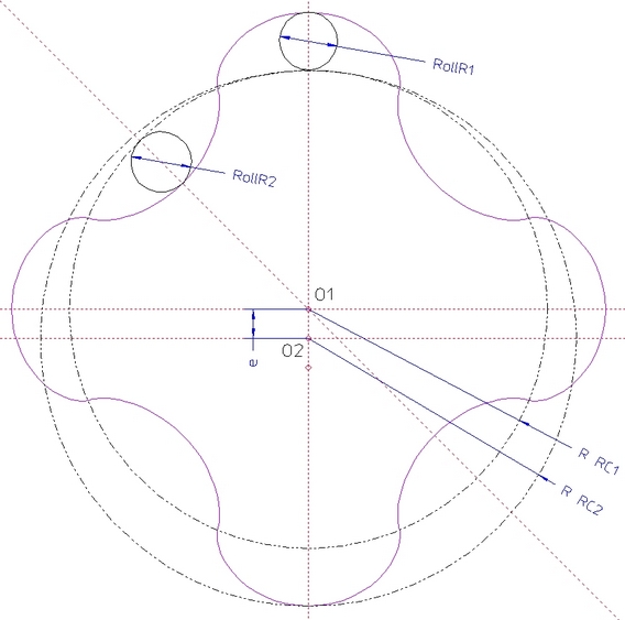
Envelope generation of 3 lobes INNER ROTOR profile starting from an 4 lobes EXTERNAL
ROTOR.
Envelope generation of 3 lobes INNER ROTOR profile (red) starting from an 2 lobes EXTERNAL
ROTOR (purple).
Calc : Calculation step [DEG] ( suggest = 0.5 ).
Dist : Minimum distance between points calculated with Calc value (suggested 0.2 mm).
JMAX : Max coupling backlash; this value allows to define the Offset value applicable to profile:
Off = ( JMAX - ( Si.min - Se.max ) /2 ) * K * (-1)
Si.min = Lover deviation of external diam. (Internal Rotor)
Se.max = Upper deviation of internal diam. (External Rotor)
K = Backlash coefficient management, is a user parameter that aims to ensure the
presence of a minimum clearance even when Iy is made with the minimum deviation
value (must be > 1 and is suggested = 1.1).
DC1 : Nominal diameter of reference circle reduced by the mean tolerance value
(Si.min+Se.max)/2.
PR : Ratio between rollers diameters ( PR=RollR1 / RollR2 must be > 1 )
GEAR2000 Help