Worm Gear
The development starts with the application of DIN 9375-1 11. 09.2012 edition of 11.09.2012, and ANSI AGMA 6022-C93 American Design Standard for Cylindrical Wormgearing, which define the
geometric shape of worm thread and wheel teeth . In addition, the standard refers to ISO / tr
10828, technical revision of the 1997: Worm gears - Worm profiles and gear mesh geometry.
The development of the procedure assumes that a kinematic-dynamic analysis project has
previously been developed that has defined the fundamental parameters of the set, among which
are essential:
Center Distance
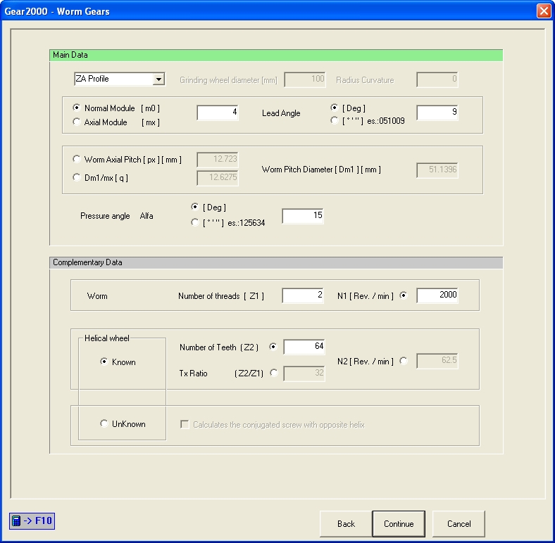
Normal Module
Pressure Angle
Transmission Ratio
Wheel teeth number
Worm threads number
“q” value (Worm Pitch Diameter/Axial Module ratio).
As for the further geometric data, in their definition, the program always refers to the DIN 867 and DIN 58400 standards, expressing them according to the screw Normal Module.
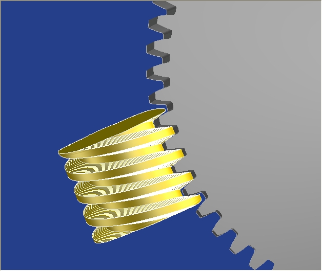
The axes of screw and wheel are always orthogonal.
For each of selectable types, the profile of the screw thread has the characteristics defined by the
Standard and is obtainable for turning, disc milling or grinding with appropriately shaped wheel.
1. Type A, ZA
2. Type N, ZN
3. Type I, ZI
4. Type K, ZK
5. Type C, ZC
6. Type H, ZH (not available).
Type A,ZA ; The axial section of the thread side has a straight profile.
Type N,ZN ; The normal section of the thread side has a slightly concave profile. The thread
space is obtainable by turning with a rectilinear side tool, positioned perpendicular to the thread.
Type I,ZI ; The axial section of the thread side has an involute profile and is obtained by
generation with a disk cutter or a small diameter grinder with straight sides.
Type K,ZK ; It has the screw side slightly convex due to the slither of the grinding wheel on the
extreme points of the thread by placing the grinding wheel at the Pitch Diameter with tilt equal to
Lead Angle.
The convexity value is the function of the diameter of the grinding wheel and the distance of the
grinding wheel with respect to the Root Diameter of the screw.
Type C,ZC ; It has the concave screw side.
The concavity of the screw side is the function of the radius applied to the grinding wheel.
The positioning center lies on the extension of the line defining the pressure angle and tool axis is
tilted of Lead Angle.
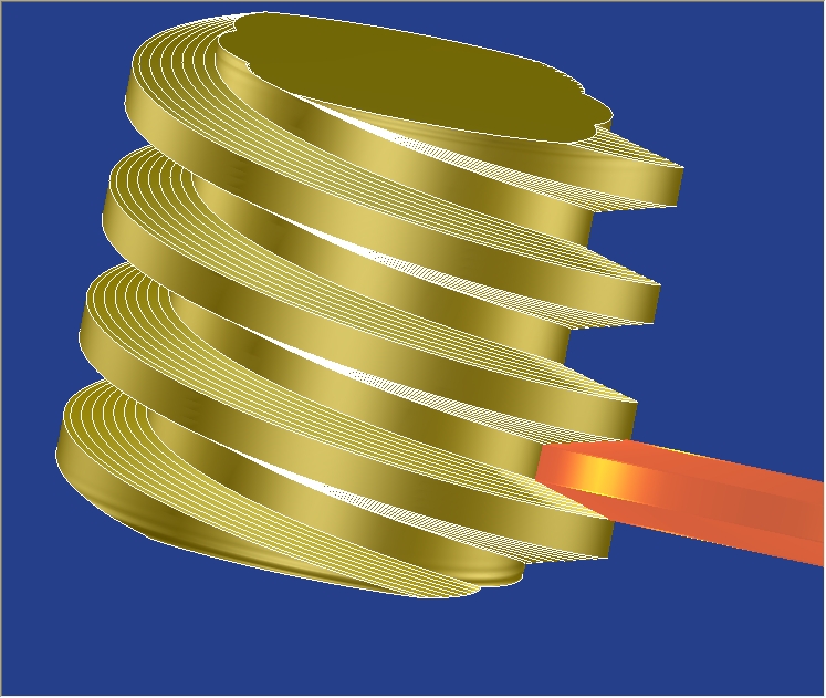
The software calculates the solid model of screw depending on the type selected and provides
the profiles of the tool for machining in a single mode:
tool positioned perpendicular to the screw axis, inclined, in the case of the grinding wheel, of the
Lead Angle.
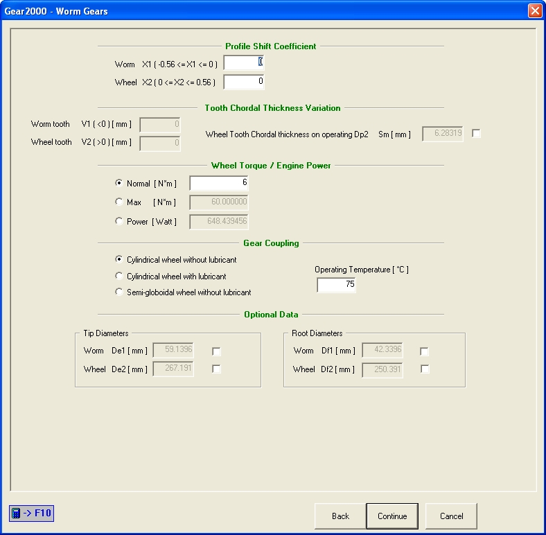
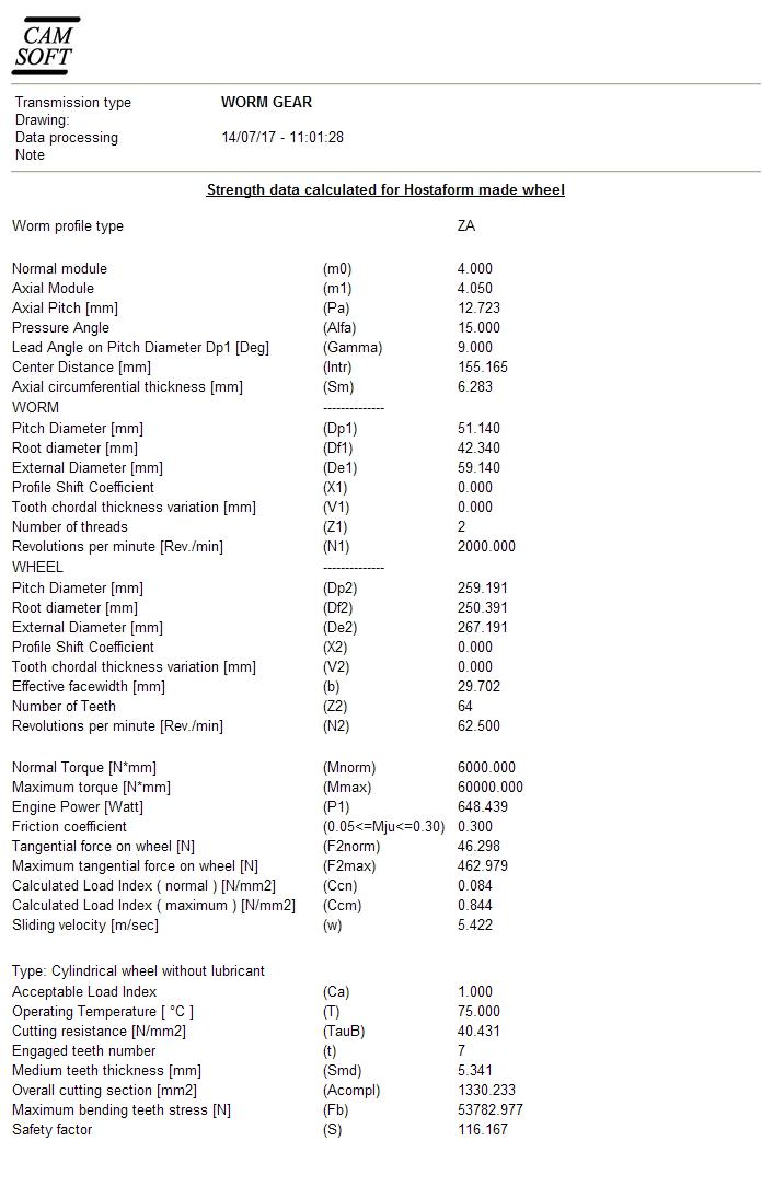
The procedure also calculates the resistance values relative to the coupling between the steel
screw and the HOSTAFORM helical gear according to the specifications already used in the
corresponding option available in the Gear2000 start menu.
Calculated data are shows into HTML report.