A screw pump is a positive-displacement pump that use one or several screws to move fluids or
solids along the screw(s) axis. In its simplest form (the Archimedes' screw pump), a single screw
rotates in a cylindrical cavity, thereby moving the material along the screw's spindle. This ancient
construction is still used in many low-tech applications, such as irrigation systems and in
agricultural machinery for transporting grain and other solids.
Development of the screw pump has led to a variety of multiple-axis technologies where carefully
crafted screws rotate in opposite directions or remains stationary within a cavity. The cavity can
be profiled, thereby creating cavities where the pumped material is "trapped".
In offshore and marine installations, a three-spindle screw pump is often used to pump high-pressure viscous fluids. Three screws drive the pumped liquid forth in a closed chamber. As the
screws rotate in opposite directions, the pumped liquid moves along the screws' spindles.
Three-spindle screw pumps are used for transport of viscous fluids with lubricating properties.
They are suited for a variety of applications such as fuel-injection, oil burners, boosting,
hydraulics, fuel, lubrication, circulating, feed and so on.
Compared to centrifugal pumps, positive-displacement pumps have several advantages. The
pumped fluid is moving axially without turbulence which eliminates foaming that would otherwise
occur in viscous fluids. They are also able to pump fluids of higher viscosity without losing flow
rate.
Each ‘screw pump' operates on the same basic principle of a screw turning to isolate a volume of
fluid and convey it. However, the mechanical design of each is different. The primary difference is
the number of screws: one, two, three or more.
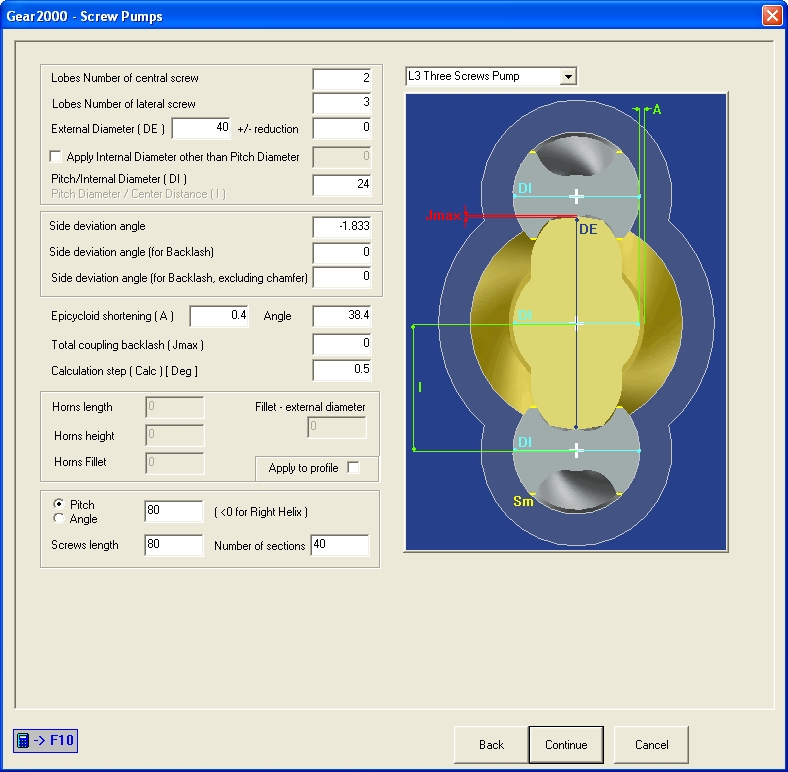
Example: pump with 2 screws of 3 lobes
'Epicycloid shortening' is a value that allows the insertion of a chamfer that convey the
rotation movement between the screws by displacing the epicycloid with respect to the primitive
diameter.
The value [mm] is associated with the next item of the menu that expresses the pressure angle
[DEG] for inserting an involute tract instead of the chamfer.
This guarantees the excellent coupling of the chamfers during screws rotation.
'Side deviation angle' are angular values that determine the rotation of the epicycloid present
in the generation profile.
More specifically:
'Side deviation angle' is a normally positive angle acting on the thickness of the lobe
by rotating the epicycloid with respect to the center of the profile (0,0).
It has effect on the generation of epitrochoid that characterizes the lateral screw.
The value is only active for 'L3 Three Screws Pumps'.
'Side deviation angle (for Backlash)' is a normally positive angle acting on the
thickness of the lobe by rotating the epicycloid with respect to the center of the profile
(0,0).
It has no effect on the generation of epitrochoid that characterizes the lateral screw.
Having no effect on the generation of the epitrochoid, allows the insertion of a
progressive side backlash.
'Side deviation angle (for Backlash, excluding chamfer)' is a normally negative
angle acting on the thickness of the lobe by rotating the epicycloid with respect to the
center of the profile (0,0).
Rotating only the contour section above the chamfer allows insertion of a backlash that
has no effect on the chamfer junction.
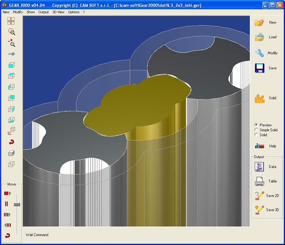
- Preview of 3D solid models without helix -
- 3D solid models with helix -
Example: pump with 3 screws of 2 lobes
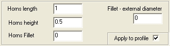
Whenever possible, you can insert the same geometric options (Horn and Fillet) directly on the
solids instead of be machined by modifying the grinding wheel shape with the options of Calculation of tool shape menu. - Shape options applicable directly to the profile -
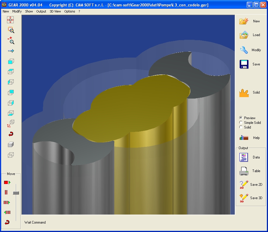
- Preview of 3D solid models without helix -
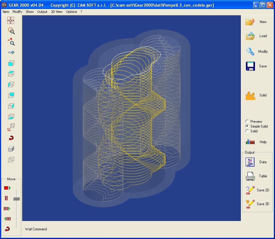
- Simple solid option of 3D models with helix -
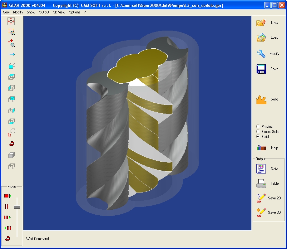
- 3D solid models with helix -
Example: pump with central screw of 2 lobes and lateral screws of 3 lobes
- Preview of 3D solid models without helix -
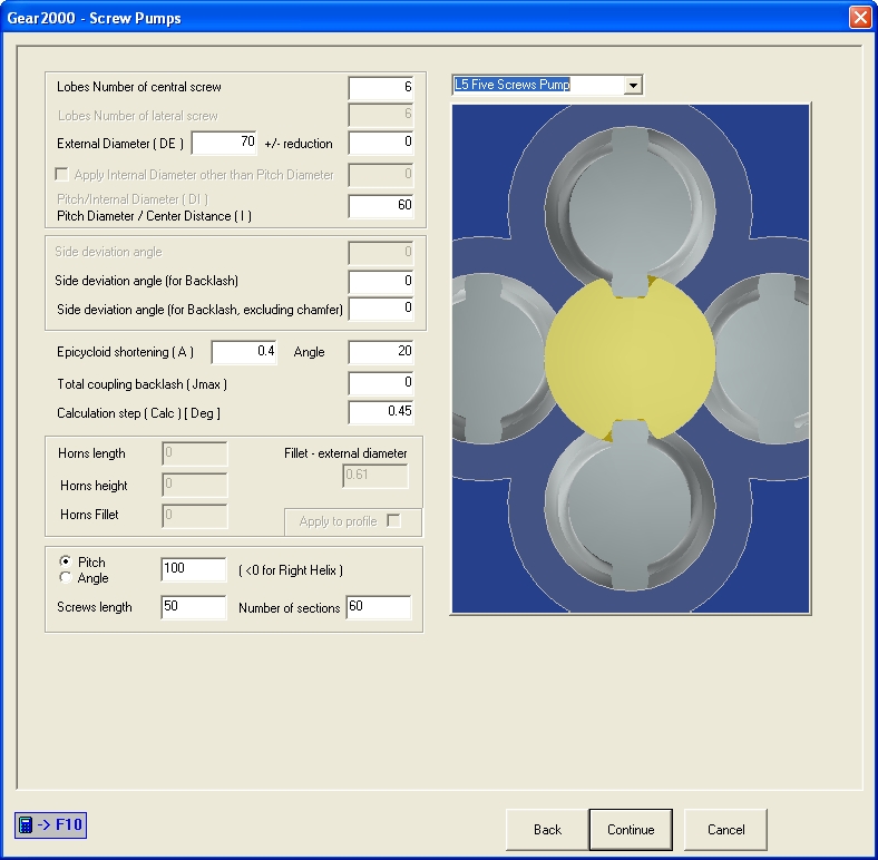
Example: pump with 5 screws of 6 lobes
Lobes Number of central screw must be even and greater than 2.
Lobes number define the tooth thickness of lateral screws and the tooth space of central screw.
Only 2 opposite lobes are used.
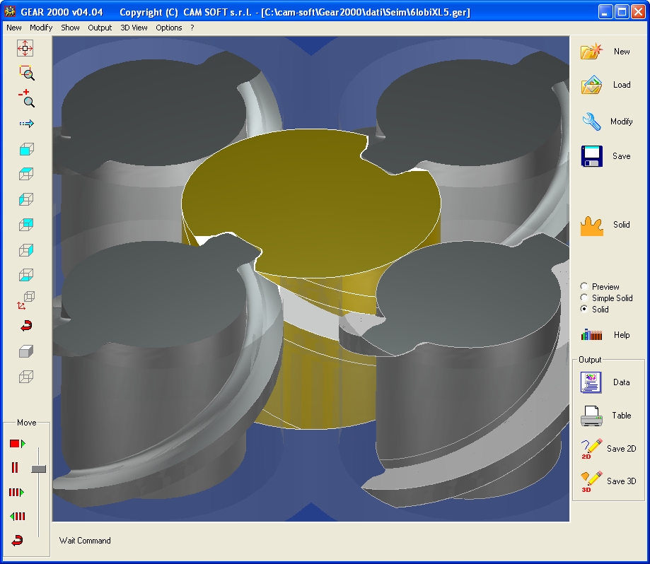
- 3D solid models with helix -
GEAR2000 Help